Content – Energy distribution
Electrical energy is energy from electrical current which is movement of electrically charged particles, which may be electrons or ions.
The movement of electrically charged particles will in normal daily life mean electricity that we receive through cables from the power plant or radio waves moving through air converted to other forms of energy by our home appliances.
Electrical current is measured in Ampere (A), which is a measure of electrical charge during a certain time. The movement occur when there exist a differential potential between two locations connected with a electrical leader (within an electrical circuit)
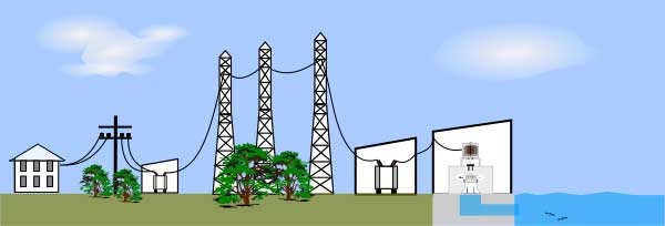
Electrical energy transmission and distribution
Electrical energy or electricity in daily life terms is distributed either by cable through distribution grids or as electrochemical energy contained in batteries.
Power is produced at voltage between 2.3 kV and 30 kV. The generator terminal voltage is then stepped up a transformer to the transmission voltage, ranging from115 kV to 765 kV AC, The voltage varies by location and the transmission system.
Energy transmisjon – Grounding of electrical systems
By connecting electrical transmission, distribution consumer systems (household or commercial) to the Earth (grounding), electrical current “leaking” due to equipment failure will be led directly to earth through the grounding conductors rather than through the body of human beings or animals.
Unless an electrical appliance is double insulated all exposed metal parts (or any orther conductor material) shall be conected to the ground cord of the equipment: When the electrical appliance is plugget into a grounded socket then the appliance will be connected to the ground cord of the household distribution system ending at the ground terminal of the fuse cabinet which again is connected to the Earth.
The use of the term ground (or earth) is common in electrical and electronics applications that circuits in portable electronic devices such as cell phones and media players as well as circuits in vehicles may be spoken of as having a “ground” connection without any actual connection to the Earth, despite. This is usually a large conductor attached to one side of the power supply) which serves as the common return path for current from many different components in the circuit.
Energy transmission – Transmission of AC (Alternating current)
High-voltage overhead conductors are normally not covered by insulation. The conductor material is sually an aluminum alloy, made into several strands, reinforced with steel strands. Improved conductor material and shapes are regularly used to allow increased capacity and modernize transmission circuits. Conductor sizes range from 12 mm2 to 750 mm2, with varying resistance and current-carrying capacity. Thicker wires would lead to a relatively small increase in capacity due to the skin effect that causes most of the current to flow close to the surface of the wire. Because of this current limitation, multiple parallel cables are used when higher capacity is neyeded. Bundle conductors are also used at high voltages to reduce energy loss caused by corona discharge.
Today, transmission-level voltages are usually considered to be 110 kV and above. Lower voltages, such as 66 kV and 33 kV, are usually considered subtransmission voltages, but are occasionally used on long lines with light loads. Voltages less than 33 kV are usually used for distribution. Voltages above 765 kV are considered extra high voltage and require different designs compared to equipment used at lower voltages.
Since overhead transmission wires depend on air for insulation, the design of these lines requires minimum clearances to be observed to maintain safety. Adverse weather conditions, such as high wind and low temperatures, can lead to power outages. Wind speeds as low as 23 knots (43 km/h) can permit conductors to encroach operating clearances, resulting in a flashover and loss of supply.[2] Oscillatory motion of the physical line can be termed gallop or flutter depending on the frequency and amplitude of oscillation.
Electric power can also be transmitted by underground power cables. Underground cables take up less right-of-way than overhead lines, have lower visibility, and are less affected by bad weather. However, costs of insulated cable and excavation are much higher than overhead construction. Faults in buried transmission lines take longer to locate and repair. Underground lines are strictly limited by their thermal capacity, which permits less overload or re-rating than overhead lines. Long underground AC cables have significant capacitance, which may reduce their ability to provide useful power to loads beyond 50 miles. Long underground DC cables have no such issue and can run for thousands of miles.
Energy transmission – Losses
Transmitting electricity at high voltage reduces the amount of energy lost. The main reason for transmission losses is resistance. The transmission line resistenace is depending on the current flowing and the length of the transmission line. Higher voltage reduces the current (for a given amount of energy) and therefore the resistive losses in the conductor. Long-distance transmission is typically done with overhead lines at voltages of 115 to 1,200 kV. At extremely high voltages, more than 2,000 kV exists between conductor and ground, corona discharge losses are so large that they can offset the lower resistive losses in the line conductors. Measures to reduce corona losses include conductors having larger diameters; often hollow to save weight, or bundles of two or more conductors.
Typically the average transmission losses in large, modern, nationwide electrical grids are in the range of 6 % – 7%.
Energy transmission – Transmission of DC (Direct current)
High-voltage direct current (HVDC) is used to transmit large amounts of power over long distances or for interconnections between asynchronous grids. When electrical energy is to be transmitted over very long distances, the power lost in AC transmission becomes appreciable and it is less expensive to use direct current instead of alternating current.
HVDC links can be used to control problems in the grid with AC electricity flow. The power transmitted by an AC line increases as the phase angle between source end voltage and destination ends increases, but too large a phase angle will allow the systems at either end of the line to fall out of step. Since the power flow in a DC link is controlled independently of the phases of the AC networks at either end of the link, this phase angle limit does not exist, and a DC link is always able to transfer its full rated power. A DC link therefore stabilizes the AC grid at either end, since power flow and phase angle can then be controlled independently.
Energy transmission – Capacity
The amount of power that can be sent over a transmission line is limited, depending on the length of the line:
- For a short line, the heating of conductors due to line losses sets a thermal limit. If too much current is drawn, conductors may sag too close to the ground, or conductors and equipment may be damaged by overheating.
- For intermediate-length lines in the order of 100 km, the voltage drop sets the limit.
- For long AC lines, system stability sets the limit to the power that can be transferred. Generally (simplified) the power flowing over an AC line is proportional to the cosine of the phase angle of the voltage and current at the receiving and transmitting ends. This angle will vary depending on the system loading and generation. Series capacitors or phase-shifting transformers are used on long lines to improve stability. High-voltage direct current lines are restricted only by thermal and voltage drop limits, since the phase angle is not material to their operation.
Energy transmission – Load balancing
Since he transmission systems do not have a large buffering capability to match the loads with the generation and since the demand is depending on many factors and cannot easily be controlled. The generation has to be kept matched to the load, to prevent overloading failures of the generation equipment.