Content – Energy generation
Various forms of turbines and engines drive electromagnetic generators:
Water turbine – Hydropower:
Power derived from the energy of falling or running water.
Types of water turbines:
There are in practical terms two main groups of turbines; Reaction turbines and Impulse tubines.
Reaction turbine:
The water changes pressure as it moves through the turbine such that the energy is transferred to the turbine shaft. The reaction turbine must be encased or fully submerged in the water flow to contain the water pressure. Pressure drop occurs in both fixed and moving blades turbines.
Reaction turbines are used in low or medium head applications (< 30 m – 300m) which means that are broadly used in dam and large power plants.
Types of Reaction turbines:
- VLH turbine
- Francis turbine
- Kaplan turbine
- Tyson turbine
- Gorlov helical turbine
Kaplan turbine

Francis turbine

Impulse turbine
The direction and velocity of a water jet changes as the jet hit and pushes on the turbine’s curved blades. The resulting change in momentum causes a force on the turbine blades. The turbine is spinning and thefore the force acts over a distance such that the diverted water flow is left with reduced energy. The water pressure is converted to kinetic energy by a nozzle prior to hitting the turbine blades. The turbine does not require a housing for operation since no change in pressure occurs over the turbine blades. All work output is due to the change in kinetic energy of the water.
Impulse turbines are often used in high head applications (>300 m).
- Types of Impulse turbines:
- Water wheel
- Pelton wheel
- Turgo turbine
- Cross-flow turbine (also known as the Bánki-Michell turbine, or Ossberger turbine)
- Jonval turbine
- Reverse overshot water-wheel
- Screw turbine
- Barkh Turbine
Pelton turbine

Formula
The power available from a certain hydropower resource may be determined by calculating the hydraulic head and the flow rate of the water.
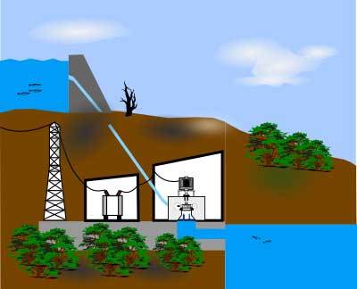
Typical hydropower plant
Power from falling water (P):
P = ηρQgh
P = power (W)
η = efficiency factor of the turbine
ρ = density of water (Kg/m3)
Q = the water flow (m3/sec)
g = the acceleration due to gravity (m/sec2)
h = the height difference between inlet and outlet (m)
Example:
The outlet from a water reservoir is located 400 metres above the inlet of the powerplant hydro turbine; The density of water is 1000 kg/m3, the water flow is 60 m/s with a feedpipe cross section of 1m2, the gravity is 9,81 m/s2 and the efficiency factor of the turbine is 90%:
η = 90%
ρ = 1000 Kg/m3
Q = 60 m3/sec
g = 9,81 m/sec2
h = 400 m
P = 0,9*1000*60*9,81*400 = 211 MW, which is the theoretical output from the turbine shaft. The actual output is pending on local conditions such as environmental factors and various loss factors through the system.